Equations below, gives forces and moments induced from package external pipework, which shall be minimum allowance in the calculations.
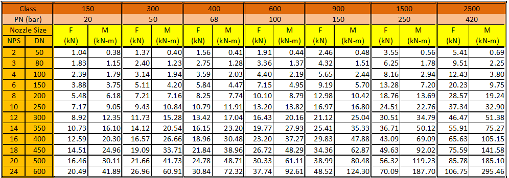
M = 4x(DN-25)1.4+2x10⁻⁵xPNx(DN)2.7[Nm]
F = 7.5x(DN)1.2+0.1xPNx(DN)1.2[N]
PN in bar and DN in millimetres.
Forces and moments are acting at the nozzle to shell junction and at skid edge for piping nozzles. The equations does not apply to equipment nozzles within package units interconnected to each other with Supplier's piping.
The moment ‘M’ (Nm) and the force ‘F’ (N) shall be applied simultaneously in:
- two perpendicular directions at the right angle to the axis of pipe or in the plane tangent to the pressure retaining part at the nozzle-to-shell interface;
- direction perpendicular to the above plane.
Whenever relevant, the stress analysis shall be done both for the radial force pulling outwards together with the internal design pressure and for the same force pushing inwards with zero pressure resp. vacuum.


